Working Principle
At ENARC ENA series, springs are installed in stator frame applies pressure to braking flange. The shoe contacts with brake flange and motor endshield flange then brake stops shaft.
When power on, the winding provides a magnetic field in the brake stator. The strength of the magnetic field beats the force of the springs. Release the braking resistor on the shaft and allows it to rotate freely.
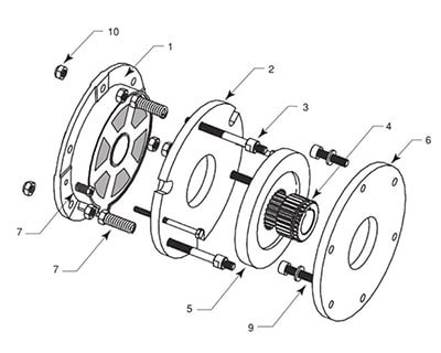
| 1- Bobin Seti / Coil Set 2- Armatür Plaka / Armature Plate 3- Ayar Vidası / Adjustment Screw 4- Dişli / Gear 5- Balata / Shoe 6- Balata Baskı Diski / Shoe Pressure Disc 7- Baskı Yayı / Pressure Spring 8- Gövde / Stator 9- Montaj Civatası / Connecting Screw 10- Somun / Locking Nut |
 |
|
ENA Serisi Teknik Bilgiler / ENA Series Technical Informations |
|||||||
|
ENA Tip / Type |
Gövde Frame |
Güç Power (W) |
Tork Torque (Nm) |
Gerilim Tension (V) |
Akım Current (A) |
Maksimum Dönme Hızı Max. Rotation Speed (d/dk - rpm) |
Çalışma Hava Boşluğu Working Air Gap (mm) |
|
ENA-13 |
71 |
60 |
5 |
220V AC |
0,11 |
3600 |
0,30 |
|
380V AC |
|||||||
|
ENA-23 |
80 |
70 |
8 |
220V AC |
0,11 |
3600 |
0,30 |
|
380V AC |
|||||||
|
ENA-33 |
90 |
80 |
15 |
220V AC |
0,35 |
3600 |
0,40 |
|
380V AC |
|||||||
|
ENA-43 |
100 |
90 |
30 |
220V AC |
0,35 |
3600 |
0,40 |
|
380V AC |
|||||||
|
ENA-53 |
112 |
120 |
40 |
220V AC |
0,60 |
3600 |
0,50 |
|
380V AC |
|||||||
|
ENA-63 |
132 |
200 |
80 |
220V AC |
0,60 |
3600 |
0,50 |
|
380V AC |
|||||||

|
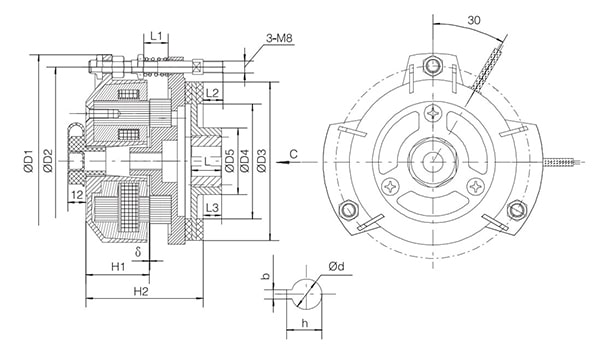
ENA Serisi Teknik Ölçüler / ENA Series Technical Dimensions |
|||||||||||||||
|
ENA Tip / Type |
d |
b |
h |
D1 |
D2 |
D3 |
D4 |
D5 |
L |
L1 |
L2 |
L3 |
H1 |
H2 |
δ |
|
ENA-13 |
14 |
5 |
16,3 |
135 |
120 |
105 |
76 |
38 |
20 |
15 |
12 |
11 |
37,5 |
72,9 |
0,4 |
|
ENA-23 |
17 |
5 |
19,3 |
141,5 |
125 |
105 |
76 |
44 |
20 |
15,5 |
12 |
11 |
41 |
76,4 |
0,4 |
|
ENA-33 |
20 |
6 |
22,8 |
156 |
140 |
127 |
97 |
52,5 |
20 |
14 |
12 |
11 |
40,5 |
77,9 |
0,4 |
|
ENA-43 |
25 |
8 |
28,3 |
180 |
162 |
140 |
100 |
60 |
25 |
15 |
15 |
18,5 |
46 |
89 |
0,5 |
|
ENA-53 |
26 |
8 |
29,3 |
198 |
177 |
163 |
120 |
65 |
30 |
17 |
15 |
21 |
46 |
89 |
0,5 |
|
ENA-63 |
34 |
10 |
37,3 |
240 |
210 |
190 |
142 |
67 |
30 |
23 |
18 |
21,5 |
52,5 |
109 |
0,5 |
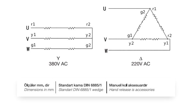
Connection Diagram
It is connected as "Y" or "∆" as shown below in accordance by the mains voltage.


